Electromagnetic interference (EMI) can disrupt your CCTV video and audio signals. There are numerous sources of electromagnetic interference, including artificial and natural sources. The consequences can range from temporary disruptions and data losses to the failure of your video surveillance system.
CCTV engineers need to be aware of the interruption electromagnetic energy (EME) can create in a surveillance environment and how to prevent them. A well-designed CCTV system should have sufficient protection from EMI to operate correctly and not interfere with other electronic equipment in the vicinity.
The British standard BS EN 50132-1 summarises the requirements for EMI compliance, requiring that all equipment be of high quality and meet the relevant EMI standards.
The standard BS EN 50130-4 defines the scope of devices that operate in the electromagnetic environments of residential, commercial, light industrial, and industrial settings.
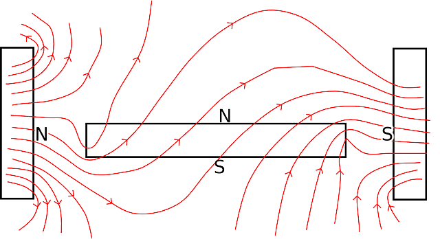
EMI (Electromagnetic interference)
One way to classify EMI is by its source, which can be naturally occurring or artificially created. Naturally occurring sources of EMI include solar radiation, cosmic radiation, electrical storms, and other similar phenomena, and artificial sources include electrical motors, fluorescent lighting, and television and radio transmitters.
The electromagnetic interference and video surveillance system
Electromagnetic interference in a video surveillance system mostly begins with either the power supply unit or the cable. Most of the time, the issue is improper grounding, insufficient shielding, or interference caused by other electronic devices. With these issues, it is essential to ensure that the power supply and cables are properly shielded and grounded.
Current leakage
Then there are the currents that leak from the main power supply onto an alternating current line and then to another device, in this case, your video surveillance system, which is also connected to the alternating current line. The video signal may be affected if the DVR or NVR is not earthed.
Radiated EMI (Electromagnetic interference)
The wireless transmission of signals from the source to the receiver is known as “radiated EMI.” One type of radiated EMI is capacitive or inductive coupling from one circuit to another. This type of coupling is commonly referred to as “near-field interference.”
Artificial electromagnetic fields (EMF)
The activities of other electronic devices in the vicinity of the device experiencing interference cause this type of EMF (also known as the receiver).
What effect does electromagnetism, or EMF, have on security cameras?
Image display interference can occur when electromagnetism is injected into the signal-carrying cable. As a result, both the video and electromagnetic signals are visible in the same image. Interference and distortion result as a result of this.
How can we reduce the risk of EMI in CCTV applications?
EMI interference management necessitates a diverse set of solutions for both emitter and receiver devices. The solution includes designing all equipment properly to reduce emissions and make the equipment less susceptible to external interference. Simple steps like increasing the distance between the source and the receiver can help. Physical orientation, such as rotating one device 90° or rerouting cables, may solve the problem.
The real solution, however, entails the proper design of all equipment to minimise emissions or make the equipment less susceptible to external EMI. Filtering, shielding, and grounding are three methods for reducing EMI.
Filtering
Passive filters work well and are widely used to reduce EMI in most electronic equipment. It usually begins with an ac line filter, which prevents bad signals from entering the power supply and powered circuits while also preventing internal signals from being added to the ac line. These shielded low-pass filters are almost universal in alternating current (AC) devices today.
Shielding
Shielding is the preferred method of containing any radiation or coupling at either the source or victim device. Encasing the circuit inside a completely sealed metallic box or other enclosure is typical. This becomes inconvenient and costly for the majority of products.
Coax cable
Cables are massive EMI sources because they act as antennas and radiate a massive amount of interfering signals. The connectors that connect the cables are just as bad. To reduce EMI, use shielded cables. Because it is self-shielding, coax is preferred. Typically, the shielding extends through the connector.
UTP cable
Unshielded twisted pair (UTP) cable is widely used in CCTV applications, especially with IP cameras. The twists assist in cancelling out the magnetic fields produced by each wire, reducing radiation. However, stray capacitive coupling causes crosstalk in the UTP. It can be made nearly as good as coax cable by using a shielded twisted pair (FTP).
Leakage through seams and openings is the main problem with shields. Seams are the points at which two metallic surfaces come together. Almost all CCTV cabling requires connecting to other devices and, in some cases, connecting to another cable to extend the cable run. The openings and gaps in the seams act as antennas, allowing radiation to escape.
Grounding
The ground, of course, is that magical common connecting point that serves as a reference for the vast majority of signal and supply voltages. The problem is that the grounds aren’t flawless. At low frequencies, such as audio and video, grounding is less important. Single-point grounds are ideal for low-frequency applications.
Testing and troubleshooting
A standard oscilloscope with a large enough bandwidth can detect some EMI. A good spectrum analyser with a wider bandwidth than your harmonics and spurious signals, such as Agilent’s X-Series (EXA and MXA), is ideal for EMC testing.
Start your accredited certification!